Traditional metal detectors rely on arm waving, one day work is very limited. If a bad terrain overgrown with weeds is unable to work. Due to the different principle, the probing depth of traditional metal detectors are very limited.
The metal detector to find a better way, I have to introduce the latest advanced technologies in the long-range detection of metal, after repeated testing. VR series developed greet depth, distance metal detection system that is kind of precious metals direction indicator.
Ultra Deep large areas characterizes by rapid scanning detection. Minutes long metal detectors to detect the size of an ordinary workload. Its signals can penetrate the mountains, figure out what gold / silver / copper three metals. The instrument is microprocessor controlled, the central unit, including abnormal correction, multi-shift programming prior to the separation of transmission and switching.
Together in the great scope of sending and receiving signals objects, the biggest measuring range of up to 500 meters. According to Hill 90 meters penetration test signal attenuation not, address the conditions in the ideal situation, The detection of a single acupuncture needle up to several meters deep. Simple equipment, not education could learn in one day.
|
It should be noted that the survey team is a rigorous process of scientific discovery of the instrument, the familiar is very necessary. Meanwhile detection is difficult. Lucky with patience, you have great success. Some of the following suggestions may help you use the right equipment:
 VR3000 Long Range Treasure Locator
- Move the equipment and accessories store in a cool dry place.
-
Cell phone, pager and other electronic equipment in use. Please do not use machines.
-
In bad weather, such as high wings and lightning, Please do not use the machine.
-
The high temperature in the weather, not the instrument under the sun 47s,They poured sand apparatus should try to avoid such foreign bodies.
-
Avoid wet equipment.
-
Equipment by preventing excessive vibration.
-
Should always check battery consumption.
-
Harder rock in the ground or in the ground, it is necessary to use tools to prevent damage antenna.
-
Practical experience in the grasp of detecting helpful.
-
Do not attempt to open the adjustment apparatus, equipment replace cement parts without exertion.
| | |
USE Guide
- Familiar with the various components of opening a box, these components include:
With a special lock boxes containing transmitters and other components. The transmitter is installed in a fixed box, a panel of six launchers LED lights Each light represents a particular function. Now in the light of a frequency selective switch, based on users need to install. Switching frequency in the following two options were those with the ※level§ of the ※ vertical § xuanniu.
Now a powers switch, charging JACK ( equipment optimized charging circuit ) and overload protection device.
Xuanniu perpendicular to the beach with levels and the corresponding light, they fired waveform used to adjust so that equipment meet the conditions on the ground. counterclockwise spin to the general state of the light response can make the greatest Department. Low rent and saline deposits in the large state to use bad addresses or darken in bright light
JACK〞the bottom two transmitter antenna is JACK, please note the correspondence between positive and negative electrodes. JACK remaining two can been removed, recharge able battery has been installed in the factory equipment. off the side panel can be replaced battery, each battery can be used for many years. In six hours before charging ahead in the use, the use of light when the work began to darken, and then give charging the battery.
Charger receiver equipped with the exclusive power adapters in use for six hours before charging ahead.
TWISTED switch of a top receiver for the amount of fine-tuning sensors.
Sets a working light, JACK charging instructions. JACK antenna and headphone Socket.
Receive antennas are sealed copper cylinder, a cylinder from the base line leads, After the merger, terminal and plug-phase ( the receiver plugs and the matching capacitance ). Each free extendable antenna.
Antenna is a red rectangular frame, leads two of the top lines in the rectangular frame, when in use JACK plugs inserted transmitter antenna ( negative attention is the counterpart ). Department of low 12 每 meter antenna was black, for marking their position.
A detailed statement of use ( on top of the sandwich box lane)
- Boot up testing
First transmission antennas linked to transmitters JACK corresponding period.
Put transmitters on the light switch to test open to the NO position. The antenna can also be places beside in a small transistor radios. 530HZ transferred to the frequency band which put to test equipment, turn on the radio, never normal. it will be radio interference, and then rotating the frequency beacons were lit up, When the light is turned on when the radio interference and everything is subject to change
- After receiving antenna packaging opened, linking it to the receiver there before the activity. Need to practice how to use it.
Received around 15 cm antenna.
Each holding out a living antenna.
Both at the distance of 30 cm.
Antenna at 15 cm distance from the first
5 cm and then balancing the normal
Walking speed to relax
Not walk 每 to increase or sloshing practice
Took him, and led antenna until the antenna to maintain balance in the move to use the antenna need some practice,
it is an effective use of this detector can be one of the skills.
- You use the master antenna in the right skills, the receiver can been fixed in front of your body. It is the best place to place the receiver. Put together the receiver and antenna Like a third step, acceptance testing antennas, this should ensure that there is no interference
- After normal working of these components can now be test for the region. Regional testing of netal 每 year 每 old films as possible.
- Regional test, launchers on the ground, the transmitter antenna connected to the transmitter JACK corresponding period. Open to the transmitter, antenna plug absolutely not, if he did, extreme damage to the equipment. In front of launchers, dug a small ditch, antennas burren ravine, no black lines Department. Frequency of the need to set to choice locations. Open launchers,then counterclockwise rotation ※ horizontal § and ※ vertical § xuanniu two of the largest, The top two light 每 until they change ( the use of transmitter to adapt to the process used to set up the ground ). In five minutes, the receiver antenna when using the above 每 practitioners, do circular motion around the antenna to maintain a distance from the antenna from five to ten meters away. If the region does not find the target object detection, antenna will not accept the cross.
- Practice with the use of this material testing instruments that study should be used to test some of the larger objects. After the skills of a few coins or visitors spent considerable weight around and test objects buried in 10 to 20 meters away from the distant transmitter.
- Repeat star 6. When you are in the firing line of the antenna and the test material, the cross should be receiving antenna ( remember : then test material and the antenna, the signal will been formed ). When you walk on this line, the receiving antenna
Use of additional proposals
Use the following additional recommendations to teach you step by step how to use the system, in the light of these plans can help you understand the proposal. Insert the antenna, the antenna can cover 360 degrees, it is the strongest regional exploration around about 60 degrees. The region is dotted performance in the regional map.
The recommend method of tracking signal
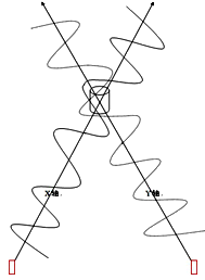
Recommend the use of signal tracking antennas to find ways around the signal line, the figure, go back and forth through the S-tracking signal line, when you the object.
Through cross chance to object orientation
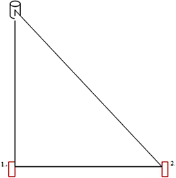
Determination rules triangular object
How difficult to reach the region through the use of the object measured triangle rules triangle object to the location, to direct attention to one location and direction. From a position of the left or shifted to the right, continually testing the location of the object, until the launch of the signal produced by the first line and angle 45degrees just as the signal line. The distance between the first position and the position is exactly the distance between the object and a place.
|
LRL03 Ultrasonic Long
Range Treasure Locator

Product Size: 46×38×18 CM
Packing Size: 50×39×26 CM
Gross Weight: 9KG
| 
|
- Introduction: LRL03 Metal Detector System:
The LRL03 Ultrasonic Long Range Treasure Locator is an advanced Metal Detector System utilizing
advanced FORWARD GAUSS technology that is both an audio and visual detector.
This metal detector was first used in the field in 1984 and the FORWARD GAUSS technology that it uses has proven to be (by far) the most successful.
This system was originally developed for professional archeologists and treasure hunters and has been used both on land and under water.
With the development of faster and more complex processing units and a reduction in the cost of materials, we were able to begin offering this breakthrough technology to the general public at a much more affordable cost.
Part of the success of this metal detector system is that it does not look like a standard 'metal detector' . Instead, it has the appearance of a fine, well manufactured piece of scientific equipment that one might expect to find at an archeological site.
The DDD03 Ultrasonic Long Range Treasure Locator is 'custom built' in a sturdy, hard side, padded case with two locks. The transmitter is case mounted and includes the 'Standard Six' elements with selector switch. The system includes an installed, rechargeable gel cell battery with charger, transmitting antenna, receiving rods and receiver with belt clip, headphones and user manual all inserted into the specially fitted case.
- Features and Functions:
- Most common frequencies are Bronze, Brass, Silver, Sand Gold, Rock Gold, and Jewel.
- Detecting Range: 320~3200 Foot
- Detecting Depth: 16~ 160 Foot
- After tracking target, you will have some idea of the identification and the exact pinpoint.
- The face (front) of the transmitter has six LED's (channel indicator lights) across the top;
each is labeled for a particular element.
- The face of the transmitter has 10 LEDs (100m, 200m, 300m, 400m, 500m, 600m, 700m, 800m, 900m, 1000m)
showing 10 different detecting range. And has one knob for selecting the detecting Range
Also, the face of the transmitter has 10 LEDs (5m, 10m, 15m, 20m, 25m, 30m, 35m, 40m, 45m, 50m)
showing 10 different detecting depth. And has one knob for selecting the detecting depth.
- Add one mini set with the receiver. This mini set is a kind of sensitivity increaser. It could make the model to be more sensitiver.
- Components:
- A black case with aluminum trim, a handle and two locks
- External Battery Port
- The Belt Receiver
- Sensitivity Increaser
- Head Phones
- Receiving Rods
- Battery Charger, AC/DC adapter
- Antenna
- Marker Flags
- Operators Manual
|
-
Specifications:
- Max Detection: 16~160 Foot
- Detect Range: 320-3200 Foot
- Rechargeable Battery: Continuous working 48 hours
- Power: 850mA
- Frequency: 433Mhz+/-150Khz
- Inner Storage: EEPROM 16k*8Bit
- Voltage: 9~12VDC
- Temperature Range: -40°C~85°C
- Operating Humidity: 0~95% (non-condensing)
- Ultrasonic Frequency: 400-3000Mhz+/-150Khz
- Weight: 14LBS
| |

| Direction of Operation
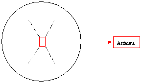 Fig 1
Fig 1
 Fig 2
Fig 2
|
After finishing all the field test of this system, placing transmitter on the ground. Plug the antenna into output jacks.
This antenna can cover 360° detecting range. The most sensitive detecting area is as the dotted lines shown in Fig 1.
PROPOSAL:
Between the antenna and your target, there is a signal line
(it is a suppositional, virtual line). You should carry the receiver rods and attach the receiver unit and walk around the antenna to find one point of the signal line. As you approach the signal line between the antenna and your target,
you will begin to hear a frequency in the headset.
When you are on the signal line, the sound will be the loudest, and the rods should cross when the line between the test target and the transmitter is crossed.
Please note, every point on the signal line should be marked.
According to above way, walk "S" for seeking the point of signal line.
And make some marks. See Fig 2.
When the rods are not crossed, you have deviated your target.
When you pass the target, the rods will turn and point the target.
|
Long Range Locator LRL04
- Introduction:
DDD04 Long Range King is our the latest model which is upgraded based on LRL03 Ultrasonic Long Range Treasure Locator
It is an advanced Metal Detector System utilizing advanced FORWARD GAUSS technology that is both an audio and visual detector.
This metal detector was first used in the field in 1984 and the FORWARD GAUSS technology that it uses has proven to be (by far)
the most successful.
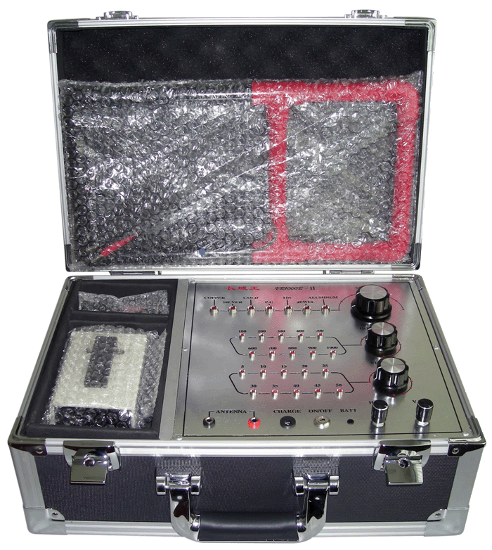

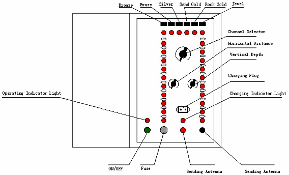
| 1. Seven Channels
2. Channel Selector

| 3. Horizontal Distance LED
4. Horizontal Distance Selector

| 5. Vertical Depth LED
6. Vertical Depth Selector

|
| 7.
| Jack of
Antenna
(Sending)
| 11.
| Horizontal
Sensitivity
Adjuster
| 8.
| Charging
Plug Socket
(Transmitter)
| 12.
| Vertical
Sensitivity
Adjuster
| 9.
| On/Off
Switch
| 13.
| Horizontal
Sensitivity
Indicator
| 10.
| Charging /
Operating
Indicator
| 14.
| Vertical
Sensitivity
Indicator
| | | |
| | | |
- Features and Functions:
- Most common frequencies are Copper, Silver, Gold, P.T, Tin, Jewel, Aluminum
- Detecting Range: 1000m
- Detecting Depth: Max. 50m
- After tracking target, you will have some idea of the identification and the exact pinpoint.
- The face (front) of the transmitter has Seven LED's (channel indicator lights for Copper, Silver,
Gold, P.T, Tin, Jewel, Aluminum) across the top; each is labeled for a particular element.
- The face of the transmitter has 10 LEDs (100m, 200m, 300m, 400m, 500m, 600m, 700m, 800m, 900m, 1000m)
showing 10 different detecting range. And has one knob for selecting the detecting Range
Also, the face of the transmitter has 10 LEDs (5m, 10m, 15m, 20m, 25m, 30m, 35m, 40m, 45m, 50m)
showing 10 different detecting depth. And has one knob for selecting the detecting depth.
- New function: adjustable sensitivity for horizontal detection and vertical detection
- New English operating panel
- The black case is adopted fireproof material
- Aluminum alloy Strawbench, English label panel.

|

|
Components:
- A black case with aluminum trim, a handle and two locks
- External Battery Port
- The Belt Receiver
- Head Phones
- Receiving Rods
- Battery Charger
- Antenna
- Marker Flags
- Operators Manual
| 
|
- Specifications:
- Max Detection: 50m
- Detect Range: 1000m
- Rechargeable Battery: Continuous working 72 hours
- Power: 850mA
- Frequency: 433Mhz+/-150Khz
- Inner Storage: EEPROM 16k×8Bit
- Voltage: 9~12VDC
- Temperature Range: -40⊥~85⊥
- Operating Humidity: 0~95% (non-condensing)
- Ultrasonic Frequency: 400-3000Mhz+/-150Khz
- Package: 1PC/CTN
Unit size: 45×32×20cm
Unit Weight: 6kg
Carton size: 46×35×25cm
Gross weight: 9kg
Pictures of Operation:
- Put half of antenna (pushing) in the ground

- Connect antenna with the machine and put the key in the on/off switch on the transmitter than
Turn on the transmitter
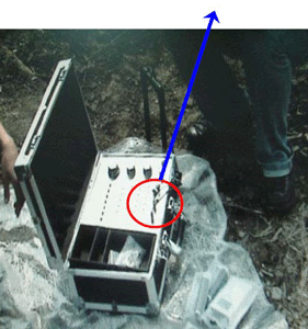

- Adjust the seven channels to select the detecting target
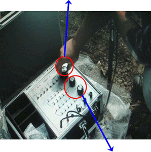
Turn horizontal distance selector and vertical depth selector to select the detecting range and detecting depth
-
Turn on the belt receiver and connected with the antenna (receiving) rods. You can set the belt receiver on your belt. Please refer to the following picture

Note All above is ready, please wait for 15 minutes, before starting to detect
- Detecting
When all above preparation is OK and start to detecting. One person take Mark Flag, another on takes the Belt Receiver and Antenna (Receiving) Rods, Move slowly around the Antenna and the transmitter, it is better 2 feet per second. And pay attention how to take the Antenna (Receiving) Rods. Please refer to the following picture

Walk around the Antenna and the transmitter in a ring.Please refer to the right picture how to walk
Note
- Keep taking the Antenna (Receiving) Rods position and parallel as the above pictures
- Must move slowly around the Antenna and the transmitter, it is better 2 feet per second
-
When the Antenna (Receiving) Rods are crossed, stick one Mark Flag in the ground to mark the cross position
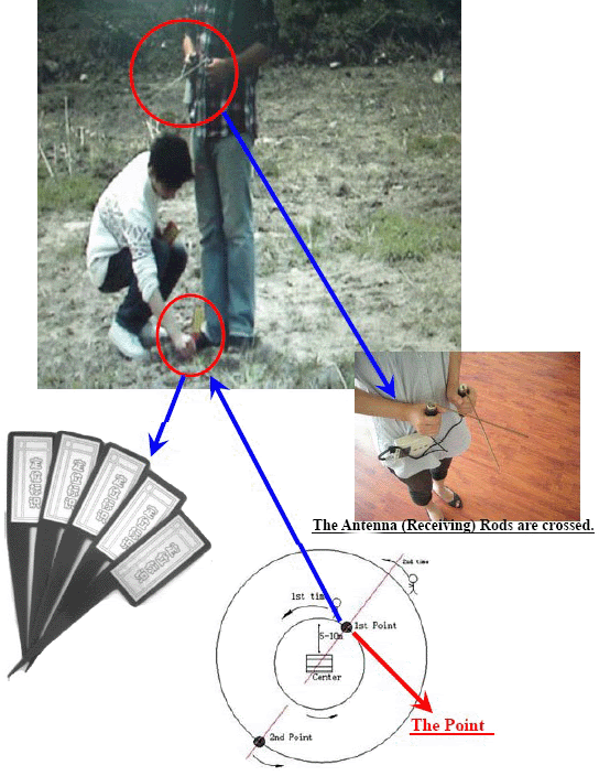
-
First walk around the Antenna and the transmitter in a ring, semi diameter is about 5-10m, to make sure a point
Then, walk around the Antenna and the transmitter in a bigger ring, semi diameter is over 5-10m, to make sure another point.
And the antenna and the transmitter and the two points are in one line, refer to the below picture

- Above is first step detecting, and change the Antenna and the transmitter position, and detect again following the above detecting method, to make sure another line.
The cross of the two lines is the position of the gold. Please refer to the below picture.

|
|


